Guide to Designing Weldments in SolidWorks
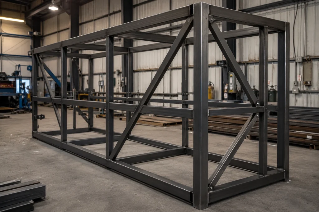
A weldment is any structure built by welding metal members together. Steel frames, machine bases, racking systems, gym equipment, trailer chassis. If it is fabricated and welded, it is a weldment. But it is worth knowing that the SolidWorks Weldments tool is useful well beyond welded metal. Timber framing, aluminium extrusions, plastic profiles, railing systems, furniture frames. If it comes in a consistent profile and length, this tool handles it.
If you have ever designed a steel frame, a racking system, a machine base, or even a timber structure, you have worked with what SolidWorks calls a weldment. At its simplest, a weldment is any fabricated structure made up of members that share a consistent cross-section profile. Welded steel is the most common application, but the tool works just as well for aluminium extrusions, plastic profiles, railing systems, and furniture frames. If it comes in a consistent profile and length, SolidWorks Weldments handles it.
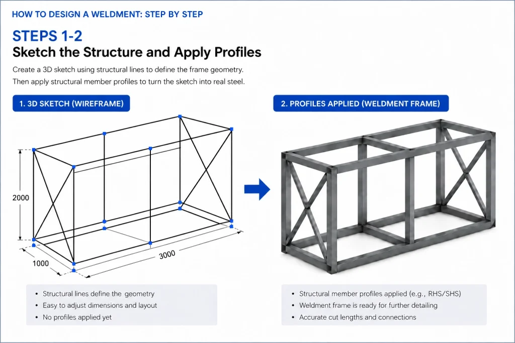
The core idea behind the Weldments environment is straightforward. Instead of modelling every tube or beam as an individual 3D solid, you sketch the structural skeleton of the frame as a series of lines, then select those lines and apply the required cross-section profiles using the Structural Member tool. Because the entire frame is driven by the sketch, changes to the overall geometry automatically update the model. This makes Weldments a much faster approach for designing anything made from structural sections, while also generating a cut list as the model develops.
What Are Weldments in SolidWorks?
A weldment is any structure built by welding metal members together. Steel frames, machine bases, racking systems, gym equipment, trailer chassis. If it is fabricated and welded, it is a weldment. But it is worth knowing that the SolidWorks Weldments tool is useful well beyond welded metal. Timber framing, aluminium extrusions, plastic profiles, railing systems, furniture frames. If it comes in a consistent profile and length, this tool handles it.
If you have ever designed a steel frame, a racking system, a machine base, or even a timber structure, you have worked with what SolidWorks calls a weldment. At its simplest, a weldment is any fabricated structure made up of members that share a consistent cross-section profile. Welded steel is the most common application, but the tool works just as well for aluminium extrusions, plastic profiles, railing systems, and furniture frames. If it comes in a consistent profile and length, SolidWorks Weldments handles it.
The core idea behind the Weldments environment is straightforward. Instead of modelling every tube or beam as an individual 3D solid, you sketch the structural skeleton of the frame as a series of lines, then select those lines and apply the required cross-section profiles using the Structural Member tool. Because the entire frame is driven by the sketch, changes to the overall geometry automatically update the model. This makes Weldments a much faster approach for designing anything made from structural sections, while also generating a cut list as the model develops.
Key Benefits of Using the SolidWorks Weldments Environment
There are engineers who still build welded structures by modelling individual parts and assembling them. It works, but it is slow, error-prone, and takes a lot more manual effort to produce documentation a fabricator can work from confidently. The dedicated Weldments environment solves all of that.
1. Speed
Draw the layout, pick the profile, and SolidWorks handles the rest. When the frame dimensions change, every member updates automatically. Without this, you are manually editing each one and hoping you have not missed any.
2. Automatic Cut List
SolidWorks tracks every member, its length, its profile, and its quantity as the model builds. Without it, you are counting sections by hand and building spreadsheets. Get it wrong and the fabricator rings you halfway through the job because they are three RHS sections short.
3. Profile Library
RHS, SHS, angle iron, channel, and I-beam sections are all available out of the box. Custom weldment profiles can also be built and saved for repeated use when standard sections do not cover what is needed.
4. Intelligent Trim and Extend
The tool handles mitre joints, butt joints, and three-way mitres automatically. Without it, you are working out every mitre angle by hand. Miss one and the cut list shows full unreduced lengths.
5. Fabrication-Ready Output
Everything in a SolidWorks weldment starts with a sketch. For most structures that means a 3D sketch, where each line represents the centreline of a structural member. You can toggle between the X, Y, and Z planes using the Tab key, and mixing 2D sketches on specific planes with a 3D sketch is often the cleanest approach for more complex frames.
Getting the skeleton right before applying any profiles is not a small thing. A well-organised, fully constrained sketch makes every step that follows faster and easier to edit. A messy one becomes increasingly difficult to work with as the design develops, and changes that should take minutes end up taking much longer.
How to Design a Weldment in SolidWorks: Step by Step
Step 1. Setting Up the Structural Sketch
Everything in a SolidWorks weldment starts with a sketch. For most structures that means a 3D sketch, where each line represents the centreline of a structural member. You can toggle between the X, Y, and Z planes using the Tab key, and mixing 2D sketches on specific planes with a 3D sketch is often the cleanest approach for more complex frames.
Getting the skeleton right before applying any profiles is not a small thing. A well-organised, fully constrained sketch makes every step that follows faster and easier to edit. A messy one becomes increasingly difficult to work with as the design develops, and changes that should take minutes end up taking much longer.
Step 2. Applying Structural Members
Once the sketch is in place, the Structural Member tool is used to apply profiles to the sketch lines. Select the standard, type, and size from the profile library, then select the sketch entities the member should follow. Members are organised into groups, and within any single group the selections must form a continuous path or be parallel to each other.
Vertical members typically need their own individual groups because they cannot be grouped with horizontal runs. The Locate Profile button controls where the profile sits relative to the sketch line, and the mirror and rotation options are useful when the default orientation is not correct, which happens more often than you might expect on anything other than a simple square frame.
Step 3. Trimming, Extending, and Sorting the Joints
Once members are in place, the joints need resolving. Raw intersections where members meet will either overlap or leave gaps. Both produce an inaccurate cut list, which means the fabricator is working from incorrect lengths.
The Trim and Extend tool handles this. You select the body to be trimmed and the boundary to trim to, which can be another body or a face or plane depending on the geometry. Corner treatment options within the Structural Member feature let you control how members meet, whether that is a mitre, a butt joint, or a three-way mitre where three members come together at a single point. This step is not optional. Skipping it does not just affect how the model looks. It breaks the cut list.
Step 4. Adding Gussets, End Caps, and Weld Beads
Gussets reinforce joints that carry significant load. End caps close the open ends of hollow sections for aesthetic or protective reasons. Weld beads represent the welds in the model and carry weld type and size information through to the fabrication drawings.
One thing worth knowing here: solid bodies like gussets need a bounding box created for them so they carry dimensional properties into the cut list. Right-click the cut list item in the Feature Manager and select Create Bounding Box. A lot of people miss this until they are looking at a drawing and the gusset entries are missing the properties they need.
Step 5 - Reviewing and Editing the Cut List
SolidWorks builds the cut list automatically as the model develops, but it always needs a thorough human review before it’s released for manufacture. Check every entry, add custom properties including material grade, finish specification, and part descriptions, and make sure the lengths reflect the actual cut lengths after all joint trimming has been completed.
A clean, fully populated cut list at this stage means the fabricator gets everything they need in one package. Every question that gets answered here is a phone call or email that does not happen later in the job.
Step 6: Produce Fabrication Drawings
This is the step that determines whether the whole project runs smoothly or turns into a back-and-forth. The Select Bodies function lets you show individual members in separate views without creating additional files. The Relative View tool handles members that were modelled at an angle and need reorienting to read clearly on the 2D sheet.
A complete fabrication drawing needs a cut list table, weld symbols, part callouts, overall dimensions, and clear material and finish callouts. If any of those are missing when the drawing leaves the design office, someone on the shop floor will have to make a decision that should have been made at the design stage.
Weldment Profile Selection and Custom Profiles
Selecting a structural profile is not just a geometric decision. It is an engineering one, and getting it right matters as much as sizing the section correctly. Rectangular and square hollow sections handle combined bending and torsion well, which is why they are the default choice for most fabricated frame structures. Angle iron and channel sections are better suited to lighter secondary members, brackets, and connection details. I-beams carry heavy bending loads efficiently in applications where hollow sections would either be undersized or add unnecessary weight.
Orientation is part of this decision too. A 100x50mm RHS loaded across its 50mm face behaves very differently to the same section loaded across its 100mm face. The stronger axis needs to be aligned with the primary load direction, and this should be a deliberate choice in the model rather than a consequence of however the profile defaulted on placement.
When the standard library does not include what the design requires, SolidWorks allows custom profiles to be created. The process involves drawing the profile cross-section as a sketch, saving it as a Library Feature Part file, and placing it within a two-level subfolder structure in the correct directory so SolidWorks can find and load it. Wall thickness, corner radii, and joint behaviour all need careful consideration when designing a custom profile.
Custom profiles are a genuinely valuable feature for many manufacturing teams. They give complete flexibility over cross-section geometry and make it possible to build a library of profiles specific to a company’s own products, standards, or fabrication processes, rather than being limited to generic sections. The standard library is worth checking first since it covers a wide range of common structural requirements, but where a design calls for something specific, setting up a custom welments profile is a worthwhile investment rather than a compromise.
Structural Thinking Before You Open SolidWorks
Before diving into the practical steps, it’s worth pausing on the structural thinking that shapes every decision when designing weldments in SolidWorks. A weldment model is only as good as the engineering thinking that went into it before a single line was drawn. Four questions are worth having clear answers to before the sketch is started.
Where are the loads going?
Every frame has primary load-carrying members and secondary ones. The structure should be designed around where the loads actually travel, not around what looks geometrically balanced on screen. Placing a heavy section where the load never goes, and a light one where it does, is a common consequence of designing for appearance rather than function.
Is the profile oriented correctly?
The bending stiffness and strength of a structural section depends heavily on which axis it is loaded about. A rectangular hollow section oriented the wrong way can be two or three times weaker than the same section correctly placed. This is a decision that needs to be made deliberately, not left to a default placement that happened to look right in the model.
Can it actually be welded?
A joint that looks clean and fully resolved in SolidWorks is not always a joint that can be physically welded in a workshop. Three or more members meeting at the same point, members close together with no torch access, or fully enclosed internal joints are all situations that can look perfectly fine in CAD and cause serious problems on the bench. Every joint in the design should be checked for physical accessibility before the model is signed off.
What happens when the heat goes in?
Welding introduces heat, and heat causes metal to move. On small components this is manageable. On long members, large frames, or structures with heavy weld sequences, distortion can take the finished part significantly out of tolerance. Weld sequence, joint type, member sizing, and the use of fixturing all play a role in controlling how much movement occurs. These are decisions that need to be considered at the design stage, not discovered during fabrication.
Common Weldment Mistakes Worth Avoiding
Most problems when designing weldments in SolidWorks are not difficult engineering failures. They are process gaps that could have been caught at an earlier stage. A poorly organised 3D sketch that felt manageable at the start becomes very hard to edit once the design has developed, and what should be a quick dimension change turns into significant rework. Skipping the Trim and Extend tool step leaves members at their full lengths in the cut list, which means the fabricator is cutting to the wrong numbers.
Not filling in the custom properties, and skipping proper use of the Structural Member tool, sends incomplete fabrication drawings to the shop floor, and the missing information always gets asked for at the worst possible moment. Getting profile orientation wrong introduces weakness into the structure that is invisible in the model but very real under load. And designing joints in CAD that look clean but cannot physically be accessed by a welder creates problems that only surface once fabrication has already started.
What Can You Use SolidWorks Weldments For?
The range of applications is broader than most people expect when they first encounter the tool. The obvious use cases are steel frames, machine bases, and structural supports, but SolidWorks Weldments is equally well suited to street furniture, gym and fitness equipment, vehicle chassis, trailer frames, industrial platforms, retail display structures, and even timber framing and aluminium extrusion systems. Any design that uses a consistent profile repeated along a path or across a structure can be built more efficiently in the Weldments environment than anywhere else in SolidWorks.
At JOA Designs, we use SolidWorks Weldments regularly across a wide range of fabricated steel projects. Our portfolio includes gym squat racks, hydroponic growing systems, street furniture, and commercial tail lift structures, all designed in SolidWorks and delivered with complete, fabrication-ready documentation.
Frequently Asked Questions
1. Can SolidWorks Weldments be used for materials other than steel?
Yes, and this catches a lot of people off guard. The tool is completely material-agnostic. Profiles can be assigned any material in the cut list, including aluminium alloys, stainless steel, timber, and engineered plastics. The name suggests welded steel, but the Weldments environment works for any structure that uses consistent profiles repeated along a path, regardless of how those members are joined or what they are made from.
2. How accurate is the SolidWorks cut list for real fabrication use?
When the model is built correctly, the cut list is very accurate. Every member length is driven directly by the 3D sketch geometry, so as long as the sketch is dimensionally correct and every joint has been resolved using Trim and Extend tool, the cut list will reflect the actual cut lengths. The most common source of error is skipping the trim step entirely, which leaves members at their full unreduced lengths. The fabricator then cuts to those numbers and the frame does not go together correctly.
3. When should I create a custom weldment profile?
Only when the standard profile library genuinely cannot meet the design requirement. Custom weldment profiles give you complete control over cross-section geometry, but they take time to set up correctly, and need to be maintained if the design changes. Always check the standard library thoroughly before deciding a custom profile is necessary.
4. Do I need SolidWorks Premium to access the Weldments tool?
No. The full Weldments toolset including structural members, the profile library, Trim and Extend tool, gussets, end caps, cut lists, and fabrication drawing tools is available in SolidWorks Standard, Professional, and Premium. You do not need a higher-tier licence to use any of the features covered in this guide.
5. What's the best approach to designing weldments in SolidWorks for complex frames?
Break the structure into logical groups before you start sketching verticals, horizontals, and diagonals each as their own group and resolve joints with the Trim and Extend tool as you go rather than leaving it all until the end. This keeps the sketch manageable and the cut list accurate throughout the build, which is the single biggest factor in designing weldments in SolidWorks successfully at scale.
Conclusion
Designing weldments in SolidWorks is one of those workflows that feels significantly more straightforward once the fundamentals are properly understood. The tool is powerful, but what separates a weldment that goes smoothly from one that causes problems at every stage downstream is rarely the complexity of the software. It almost always comes back to the same three things: a clean and well-organised sketch, joints that have been properly trimmed so the cut list reflects real lengths, and a cut list that has been fully populated with the material and finish information the fabricator actually needs.
Get those fundamentals right and everything else in the process follows naturally. The drawings are cleaner, the fabricator has fewer questions, and the finished structure arrives on site the way it was designed.